📊 Weigh Your Ideas, Measure Your Success!
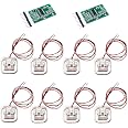
This DIY kit includes two 50kg load cell sensors and an HX711 A/D amplifier, designed for high precision electronic scales. It supports multiple configurations for various weight capacities, making it ideal for hobbyists and professionals alike.
N**N
a little fidgety but I got it working.
I ran mine into a nodemcu.I found one of the amplifiers was dead but it may have been my fault, I initially hooked it into the 5v feed.I found a great tutorial on youtube that showed how to setup a whetstone bridge with the hx711 and that set me on the right path.The most challenging part which I didn't initially understand was to route out a board to set the sensors into so they were suspended properly in such a way to allow a reading. Initially I just hot glued them flat to a board and that doesn't work. I used a 1" forstener to make a 1/4" deep hole in a piece of plywood and then glued them in place. In the next iteration I'll go dig for 3d printed feet since I've seen reference above to that.
M**T
<UPDATED> Not functional. Might be knockoff chips <Boards are wired wrong!>
The 1st photo shows a board with "MH" stamped on it. The actual chips they sent do not. They are different and look like the ones shown in photo 3. The boards are physically different. There is a lead from the HX711 "rate" to GND which is supposed to set the rate at 10 SPS per the data sheet. The HM chips don't have this (maybe imbedded, not sure). Other than that, I'm not sure the all the exact differences in the board. All I know is that they don't work.I bought a single board and 4 gage package from a different seller. It had a HM printed on the board. When hooked up to an Arduino, everything works fine. The chips reads (as well as the system can anyways)Since this one worked for my project, I ordered 2 sets of 2 each from this seller (so I could have a total of 5). figured I'd save a few buck getting them 2 at a time. They do NOT work. I tried everything including writing a bit-banging sketch to verify that it just wasn't incompatible with the HX771 library I was using. They don't work. The program hangs up after the first (erroneous) reading. I've tried 3 different HX711 libraries. I tried physically cutting the "rate" lead on the board (even though this should be correct per the HX711 data sheet). Nothing. The 4 boards from this seller do not read. The one with the MH does fine. There's something wrong with these. I don't know exactly what, but there is something wrong.<UPDATE 5/28/24>OK, so after pulling out my hair for more time than I wanted, I figured it outThese boards are not wired properly. There is a pin for AGND on the HX711 chip that needs a ground. it's right there in the diagrams they have attached. instead, they just wired it to "-E". There's enough voltage bleed to totally screw up the circuit. This is bad design and incorrect.There is a solution... wire a jumper from -E all the way over to Ground. That got them working again. reading seem normal now. Although you shouldn't have to rewire a faulty design.
A**J
The signal isn’t stable over time.
You have to continually tare the weight and even then it’s not very accurate and unstable
O**T
Does the job - Here's my "Hello World" wiring example...
My biggest complaint with this is that there isn't enough documentation I could find with examples for common platforms and specific wiring instructions. But once I finally found and processed what I needed to know, it seems to work pretty well with my Pi Pico board here. For anyone else struggling to get two of these wired up, wondering if there need resistors involved or if some leads should be connected to supply voltage / ground: STOP. Just stop all of that. It's much easier than that. This is what worked for me, to wire up two to one HX711:Connect the white wire of one unit to the black wire of the other - connect both to E+ inputConnect the other white / black wires together and connect those to E- inputConnect the red wires to A+ / A- inputsConnect HX711 "DT" and "SCK" to Pico/etc GPIO pins (does not need to be analog), connect power and ground.From micropython, install HX711 (with upip or just find and save the file to the device manually)from HX711 import hx711driver = HX711(d_out = {the GPIO pin# you connected "DT" to}, pd_sck={the GPIO pin# you connected "SCK" to})driver.read()-> 45321and that's it. You'll have to calibrate it to an implementation specific minimum / maximum value within your code, how you actually mount it and what weight it holds without any load all change the specifics too much for a generalized solutionGood luck!I'm not sure if it matters which one goes to which (e+ versus e-, a+ versus a-), my setup here has worked like that with the first selection, I suspect it works either way.
B**
its good for fun, anything else it doesnt really do much.
If you want to play around with a sensor and just have fun is okay, but if it's for something important, get something else.
A**.
Load Cell Amplifier NOT working HX711 not found
Load Cell Amplifier NOT working" HX711 not found" not find in programDo Not Buy
F**G
work well
I had written a detailed review, but Amaz0n deleted it because it points to URLs that are not Amazon, but Github. Yeah, this company feels threatened by github. I pointed to a place where you could get plans for 3d printing feet. Also,to yaml scripts that allowed you to nicely set up these sensors on ESPHome. But that was all deleted. So, I regret buying them here and not from a less evil company.But that is not the fault of the seller. I created two identical setups. One worked, and one did not. Debugging shows that (at least) one of the load cells does not work. I wish that there were an easy way to test each of them.
R**C
Worked as expected
Didn't have any surprises using this but i was a little dissapointed with how thin the wire for this was. Probably not even exaggerating when I say there's about 5 strands of wire inside. Makes it super hard to work with but it worked out.
Trustpilot
1 month ago
5 days ago