🎶 Elevate Your Audio Game with DIY Precision!
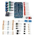
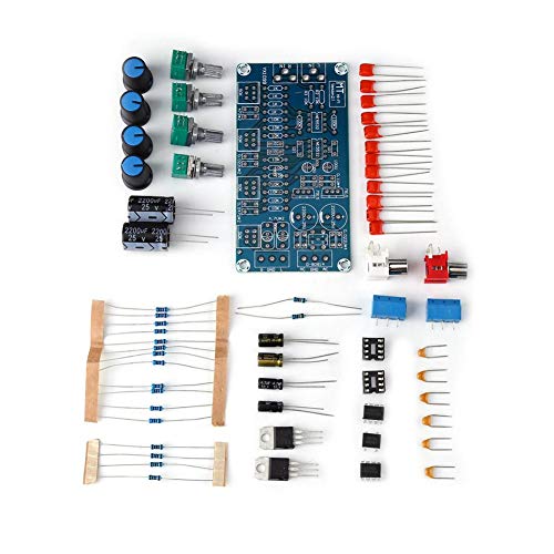
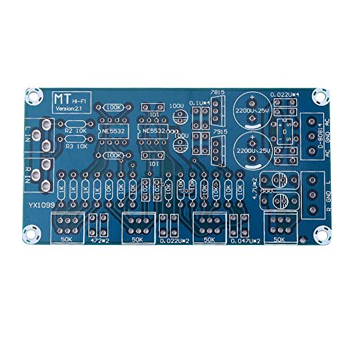
The NE5532 Amplifier Kit is a high-performance stereo preamplifier designed for DIY enthusiasts. Featuring a full bridge rectifier power supply circuit, it effectively eliminates high-frequency interference while providing a wide frequency band and low noise output. With treble, midrange, and bass tone controls, this kit allows for a customizable audio experience, making it an ideal choice for both personal projects and professional setups.
S**N
quality components, very well designed, easy assembly.
Quality components, very nice board, well designed. Easy to assemble for most experienced hobbyists. The circuit is easy to modify the shelving frequencies of the bass, mid, and treble to suite other applications such as musical, vocal, pa applications. This is accomplished by scaling down the bass caps (0.047uF) and scaling up the treble caps (2n2) by an equal amount. The mid may also be moved too in whatever direction desired.The center frequencies are approximately 20khZ, 800hZ, 20hZ as the kit comes. The overall gain is 10 and that too can be changed by the resistors around the first 5532 op-amp. Further mods are with power supply. You can eliminate the bridge rectifier and jumper + to ac terminal and - to other ac terminal if you already have DC power from somewhere else that is at least +20 volts AND -20 volts (not to exceed +35, -35 volts) plus a ground (neutral), it must be bipolar! The circuit will operate on lower voltages but will require you to put jumpers in place of the voltage regulator I.C.'s and lower voltages will reduce signal swing and hot signals may cause overload (clipping). No need to install the 2200uF caps since the 100uF and 0.022 caps are adequate for decoupling the supply and it could cause power-up surge issues somewhere else.Excellent value for the price. Board is very high quality as are the pots and components. Parts alone would well exceed the price of the kit alone. Built, modified and tested my own kit with 100% success! Very satisfied and highly recommend. Please note there are no instructions or documentation of any kind, so this kit is for more experienced builders.
F**.
Nice Clean Preamp
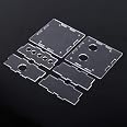
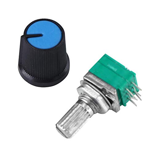
This was a fun, easy kit, no schematics or guess work.It sounded so good I bought another one for my other system.The only part that required any skull sweat was the enclosure I put it in.I have the first one rack mounted on 1/8 aluminum rack panel.The panel needed to be thinned out the allow the threads on the potentiometers enough room the accept the nuts and washers. The maximum thickness is about .065 inches. The pot shafts fit in 9/32" holes and the spacing in about .932 inches. A hair under an inch.Have fun!!!
D**.
I highly recommend this little op-amp tone/voltage preamp! It’s fun to build and it sounds great!
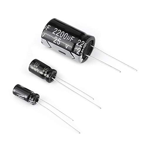
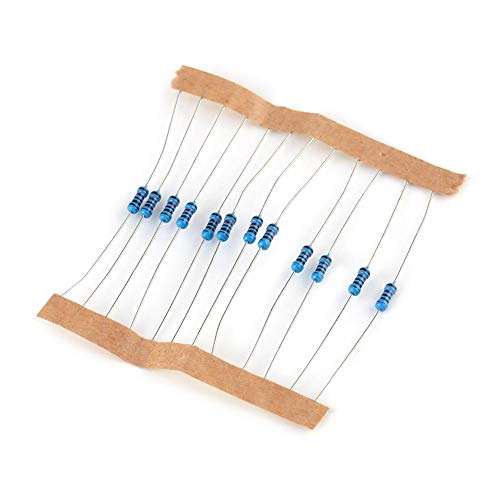
I build professional quality products using a modular approach. I chose this preamplifier because it was a do it yourself kit, and uses a very popular and very stable operational amplifier (op-amp) that provides good gain, A very good signal to noise ratio, acceptable harmonic distortion, good input impedance and with a 400-600mV input signal this will easily drive ‘any’ amp board you choose. The other niceties are numerous; if you take a good look at the circuit board, the power ground And output signal ground are isolated, (not coupled) which provides for a floating signal ground which is useful in a lot of different circuit designs s. Secondly, the engineer decided to provide for a full wave rectifier instead of a half wave so if you choose to you can use a low-cost 24vac center tap transformer (12-0-12) which, after being rectified by that full wave bridge will give you +/-17vdc as Vin on the 78/7915 linear voltage regulators, (12*1.414=16.968). This particular solution also stays in a safe zone considering that the filter capacitors that reduce AC ripple are rated at 25 V. The other cool thing is is that because there is not a significant difference between Vin and Vout, And this thing doesn’t suck a lot of current, you don’t have to heat sink the voltage regulators.The way I use these types of products is that I start with a 19 inch rack mount 2U or 3U chassis and I’ll stuff a toroidal transformer, a full wave bridge rectifier and filter cap board, an input selector board (+15vdc), a speaker protection circuit board (+12vdc), a blue tooth receiver board (+5vdc), this preamp/tone board (+/-12vac**), a low pass filter/subwoofer summing preamp (+/-18vac), a dual channel VU meter driver board (+12vdc), a dual channel fixed gain current amplifier that drives the L/R speakers w/200w @8ohms (+56vdc) and finally a single channel/mono current amplifier the drives a passive subwoofer w/500w @4ohms (+48vdc). And sometimes the person who commissions the custom built amp wants to play some vinyl, I will add a RIAA phono preamp (+15vdc).** most operational amplifiers are a “push-pull” design where the signal crosses zero volts and goes negative to positive etc. So they require dual voltages. You can design your preamplifier around a single ended Circuit so that you don’t need a negative supply but the integrated circuit choices are fewer than the push pull or Darlington type operational amplifiers. You may have noticed that I have several different voltage requirements, with a wide range of voltages in both AC and DC. To digress a little bit, I don’t pay attention to the AC voltage requirements. The diode‘s that are in a rectifier circuit, either half or full wave have a forward voltage drop of approximately 1.2 V. So in the case of the preamp that I am talking about, I’ll just feed the board +/-180V DC instead of the AC voltage. In this particular amplifier that I’m building for someone, the toroidal transformer has a center tapped secondary that gives me +/ -30vac And with a full wave bridge, that gives me (30*1.414 RMS to Peak)=43vdc. Or if I isolate my center tap, I can bridge the two secondaries and get 60 V AC and then use a half wave rectifier (2 diodes) and that way I can supply my subwoofer amplifier. To knock down these voltages I use either an LM 317 or fixed voltage “buck” converters. In this case I’ll use an LM317 and a fixed voltage converter.When I bench tested the preamp, my signal to noise ratio (A-weighted) was 92db. With a 1 kHz signal my total harmonic distortion with a non-inductive load was .062%. Quiescent current was less than 100 mA, fully cranked wide open it was about 800 mA or about 10 W. Channel separation was -66 dB. The dynamic headroom was a very impressive 102 dB! All in all this is a very pretty little amplifier. I did kludge it though. I pulled the electrolytic capacitors and dropped in two that were rated for 50 V DC because of my power supply requirements and what I had available but other than that...that’s it I did supply it with DC voltage though and I took the 1.2 volt loss, it doesn’t matter because of the linear voltage regulators that were built into the design. The finished preamp sounds warm, almost like a tube preamp. However, It did remain very crisp. I suspect that the tonal controls probably have a rolloff of 12 dB. (I got tired of using my oscilloscope so I’m just guessing here). All in all, well worth the money and the one hour it took for me to put this thing together. The components are of good quality including poly styrene capacitors, 1% and 5% resistors and shielded audio taper potentiometers. I really like the way the potentiometers feel, it’s little things like that that make a difference. The one caveat that I have is that I hate those stupid connectors that are supplied. Rarely do I ever use them, I always hard solder everything. I highly recommend this little board, it’s well engineered, it has good quality components, the circuitboard is well laid out and has isolated grounds. Go get yourself one of these and have some fun!
P**I
X001KWAA5X - Missing items
1- instructions2- (4) 10k resistors3- (1) 102 cap4- (1) .47k100 resistor
A**R
The delivered parts did not match the PCB board.
The delivered parts did not match the PCB board. Attempts to try and guess what went where were ultimately unsuccessful, as the PCB traces disintegrated. Not worth salvaging: just discarded
S**J
Works great
Easy to assemble. Worked the first time I turned it on. Sounds good.
T**R
Works great if you can solder,
Works just fine. If you know how to solder and dont mind a stationary rig, heres your $200 headphone amp with equalizers for pennies on the dollar. Took like 30mins to make. I powered with a 120/12 vac transformer from the wall.
"**"
Fun
I bought this so I could learn and so far it allowed me to do some soldering though I wonder if I soldered correctly or not which I won't know until I get to try out the unit I'm waiting on a transformer now I saw a post where somebody thought we had to use AC it's not true using it transformer to transform AC to DC but you need the positive DC and you need a negative DC and that's the reason why we're using a transformer. The thing I wish this had was a schematic so that I could learn from it like why you chose ceramic capacitors versus electrolytic capacitors, where the bridge rectifiers were put and why are they there,. I'm sure some of those capacitors and resistors were filters but it would be nice to go see where they were and why. So I guess what I'm saying is a little more documentation would have been nice especially a schematic at least with a schematic I could figure out some of this stuff but otherwise it was fun soldering the board
Trustpilot
1 week ago
2 months ago